
Selecting the Right OTDR for Fiber Testing Jilong OTDR kl-6100
10 min read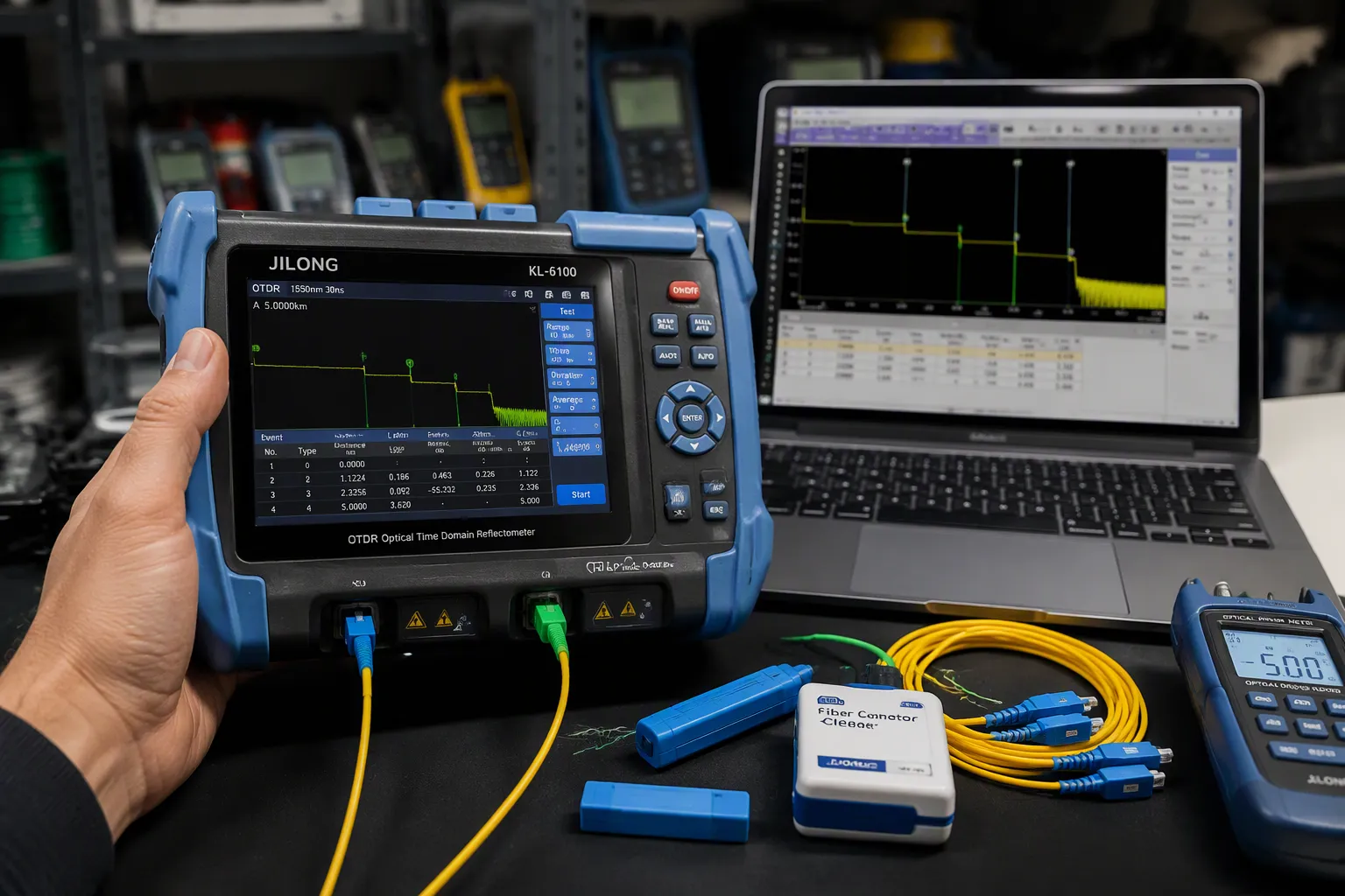
Choosing the wrong OTDR wastes your budget and yields unreliable fiber test results—here is how to avoid that. The Jilong kl-6100 provides a practical balance of accuracy, portability, and affordability for beginners. This guide shows you how to test fiber optic cables with OTDR properly, including evaluating features and comparing models. Jilong brings over 30 years of optical communication expertise (since 1993) to its OTDR product line.
Key Takeaways
- Choose an OTDR with the right dynamic range and dead zone for your fiber network.
- Always clean and inspect connectors before testing to get accurate results.
- Use a launch cable to measure the first connector and avoid dead zones.
How to Test Fiber Optic Cables with OTDR: Key Selection Criteria
An OTDR (Optical Time-Domain Reflectometer) sends a laser pulse into a fiber and measures the light that scatters back. This backscatter reveals the fiber's condition along its entire length. You use it to find breaks, measure splice loss, and verify connector quality. Without it, troubleshooting buried or aerial fiber becomes guesswork. Understanding what an OTDR does and why it matters helps you avoid costly errors.
What an OTDR Does and Why It Matters
Think of an OTDR as a radar for fiber. It fires a pulse of light and listens for the returning signal. When the pulse hits a connector, a splice, or a break, the reflection pattern changes. You read these changes on the trace to locate and characterize events. For example, a fusion splice appears as a clean step down in the trace—no spike. If you see a spike, that splice has a gap or crack and needs rework. An OTDR also measures total link loss and fiber length. This device is essential for acceptance testing, troubleshooting, and certifying a new installation.
Dynamic Range and Dead Zone Explained
Two specifications dominate OTDR selection: dynamic range and dead zone. Dynamic range tells you how far the OTDR can "see." For metro or enterprise networks, you typically need 30–35 dB of dynamic range at 1310/1550 nm. The table below shows a common benchmark:
| Network Type | Wavelengths Needed | Dynamic Range | Key Feature |
|---|---|---|---|
| Metro / Enterprise | 1310/1550 nm | 30–35 dB | iOLM / auto analysis |
Dead zone refers to the distance after a reflective event where the OTDR cannot detect another event. Two types matter:
| Aspect | Event Dead Zone (EDZ) | Attenuation Dead Zone (ADZ) |
|---|---|---|
| Definition | Distance after a reflective peak where a second event can be detected | Distance after a reflective peak where loss can be accurately measured |
| Typical Value (short pulse) | ~1 meter | ~4 meters |
| What it limits | Ability to distinguish two closely spaced connectors | Ability to measure loss of a subsequent event accurately |
Pulse width controls both range and dead zone. A short pulse (5–30 ns) gives you short dead zones but less reach. Use it for short-haul links where events are close together. A long pulse (1–20 µs) reaches farther but stretches dead zones. For example, a 5 ns pulse reduces the event dead zone to about 1 meter. A 20 µs pulse might create a 50-meter dead zone. You must select the right pulse width for the link length and event density. This is why understanding how to test fiber optic cables with OTDR starts with matching pulse width to your network.
Wavelength Options and Fiber Type Compatibility
TIA standards specify test wavelengths for each fiber type:
| Fiber Type | Standard | Test Wavelengths |
|---|---|---|
| Single-mode (SMF) | TIA-568.3-D | 1310 nm, 1550 nm (plus 1625 nm for in-service) |
| Multimode (OM4) | TIA-568.3-D | 850 nm, 1300 nm |
| OM5 wideband | TIA-492AAAE | 850 nm, 953 nm |
For single-mode fibers like G.652 and G.655, dual-wavelength testing at 1310 nm and 1550 nm covers most needs. Both fiber types support single-mode operation at both wavelengths.
Both fiber types exhibit single-mode operations for both the 1310 nm and 1550 nm bands, and represent good choices for long-haul links.
Testing at both wavelengths reveals wavelength-dependent losses. A macrobend might show 0.2 dB at 1310 nm but 5 dB at 1550 nm. This difference flags bending issues that a single wavelength test would miss. If you work mostly with single-mode fibers in campus or access networks, a dual-wavelength OTDR at 1310/1550 nm is the practical choice.
Why the Jilong kl-6100 Fits Beginner Needs
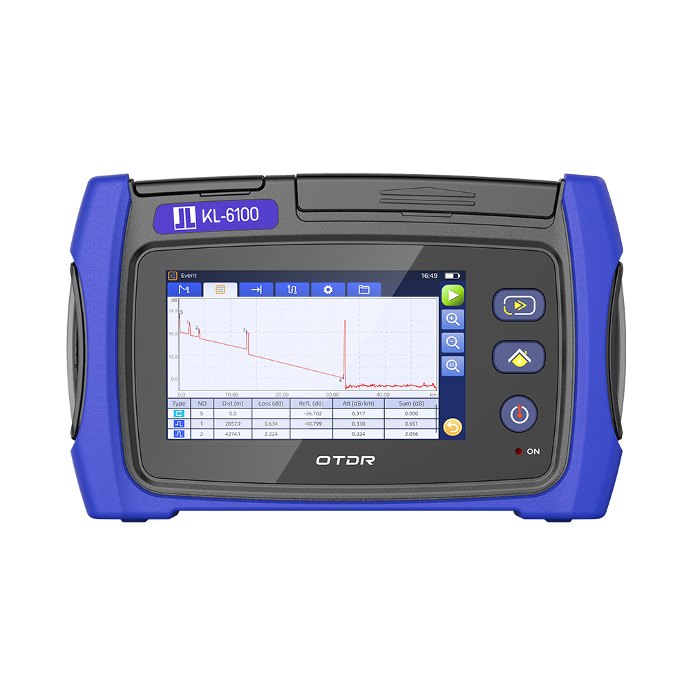
The Jilong kl-6100 delivers the essential features you need without overwhelming complexity. Its dynamic range suits typical metro and enterprise links—around 30 dB at both 1310 and 1550 nm. This covers most premises and short-haul networks up to 120 km.
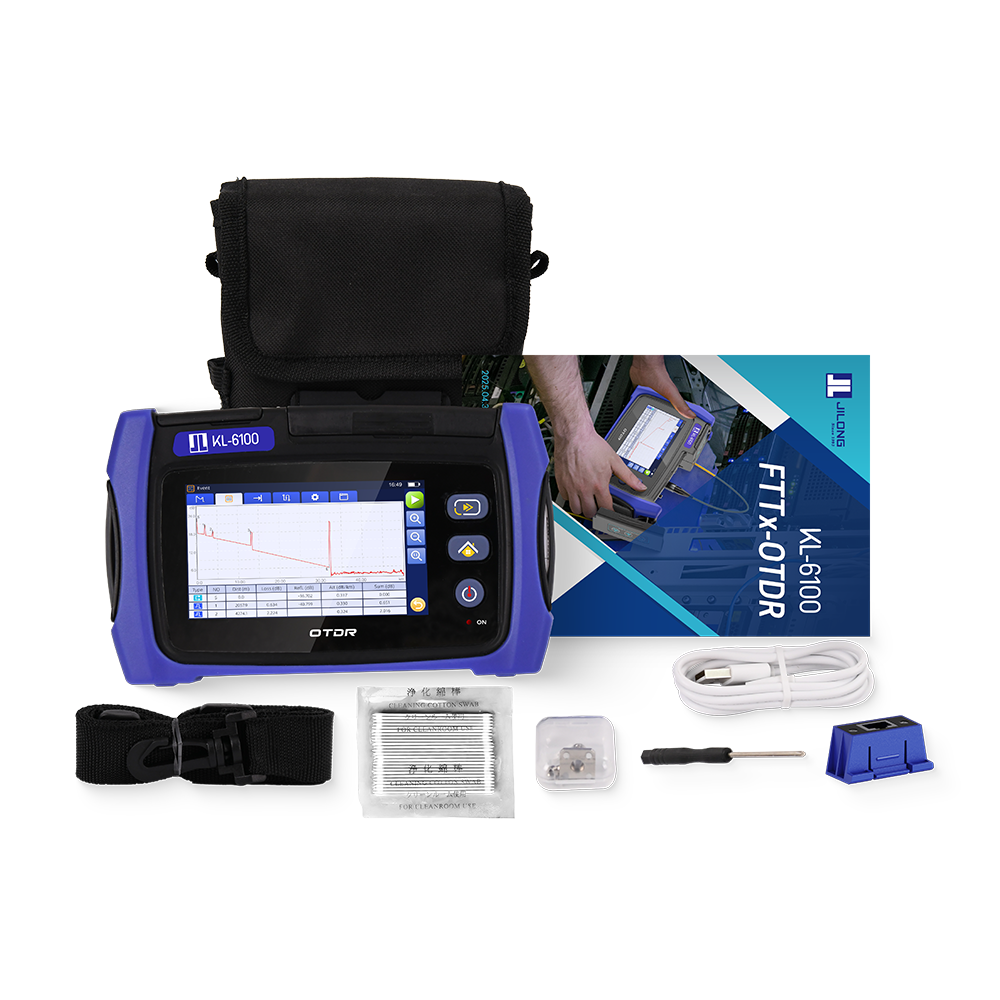
The device supports adjustable pulse width from 5 ns to 20 µs, letting you trade off range and dead zone as needed. Its short-event dead zone (under 1.5 m) and attenuation dead zone (under 8 m) mean you can spot closely spaced connectors and patch panels. The built-in dual-wavelength laser matches TIA standards for single-mode fiber testing.
At a price point around $180, it removes the cost barrier for technicians who want a reliable tool to practice how to test fiber optic cables with OTDR without investing thousands upfront. Jilong's over 30 years of optical manufacturing experience means the kl-6100 is built on proven technology, not experimental design. For a beginner, this combination of capability, simplicity, and affordability makes more sense than overspending on a high-end model with features you may never use.
Step-by-Step: Testing Fiber with the Jilong kl-6100
You have the right tool in hand. Now you need a repeatable process. The steps below walk you through how to test fiber optic cables with OTDR using the Jilong kl-6100, from the first connector inspection to the final trace review. Follow them in order. Each step builds on the one before it.
Setting Up the Device and Launch Cable
Preparation decides whether your trace is clean or cluttered. Start by turning on the kl-6100 and letting it warm up for five to ten minutes. This stabilizes the laser and improves measurement consistency. While the unit warms up, inspect and clean every connector you plan to mate. Use a fiber inspection scope on each endface. Clean with a one-click cleaner sized for your connector—2.5 mm for SC, FC, and ST, or 1.25 mm for LC and MU. Re-inspect after cleaning. The rule is simple: inspect, clean if needed, inspect again, then mate. Never skip this step. A single dust particle on the fiber core can add loss and reflections that look like real faults on your trace.
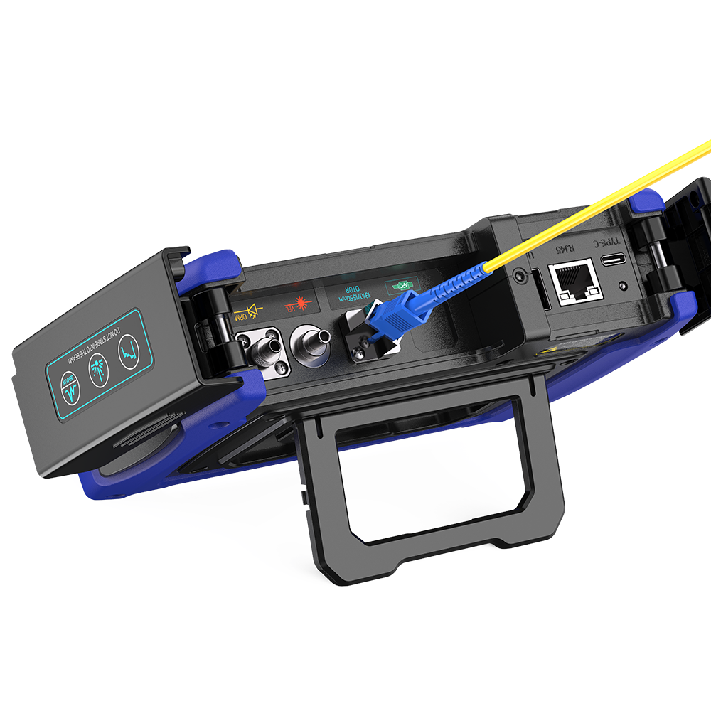
Next, attach the launch cable. A launch cable is a known-length fiber reel that connects between the OTDR port and the fiber under test. Its job is to push the OTDR's dead zone away from the first connector you want to measure. Without it, the first connector sits inside the dead zone and you cannot measure its loss. Choose a launch cable longer than the OTDR's event dead zone at the pulse width you plan to use. For the kl-6100, a 150 m launch cord works well for links of 2 km or less, which covers most enterprise and premises networks. The table below shows common recommendations by application.
| Application | Recommended Launch Length |
|---|---|
| Premises / LAN cabling (short links) | 100–500 m |
| Data center interconnect (DCI) | 100–500 m |
| Outside plant (OSP) / metro fiber | 500–1,000 m |
| FTTx / PON network commissioning | 500–1,000 m |
| Long-haul / submarine cable testing | 1,000–2,000 m |
| Aerial and underground cable acceptance | 500–2,000 m |
A useful rule of thumb: pick a launch cable at least 1.5 times the event dead zone at your chosen pulse width. For most field OTDRs, 500 m handles short-range testing, while 1,000 m or 2,000 m suits long-haul or high-dynamic-range work. Patch cords are only 1–3 m long and are far too short to clear the dead zone. You need a proper launch reel of at least 100 m for accurate measurements. Connect the launch cable to the OTDR first, then to the fiber under test. This order prevents you from accidentally exposing the OTDR port to a dirty connector.
Connecting and Acquiring a Trace
With the launch cable in place, connect the fiber under test to the far end of the launch cable. If you are testing a bulk fiber spool, no far-end termination is required. For a complete link, attach a receive cable at the far end if you want to measure the last connector. Now configure your test parameters. The kl-6100 supports auto-test mode for routine work and manual setup for acceptance testing. For single-mode fiber, test at 1310 nm and 1550 nm. For multimode, use 850 nm and 1300 nm. Set the range slightly longer than the expected fiber length. Choose your pulse width based on the trade-off between resolution and reach. A short pulse gives you fine detail but less distance. A long pulse reaches farther but stretches the dead zone.
Once your parameters are set, initiate the test. The kl-6100 sends pulses into the fiber and builds the trace over several seconds. Auto-test mode works well for quick checks, but it is not foolproof. Most OTDR testing problems occur when untrained users rely on auto-test without understanding what a good trace looks like. Watch the trace as it builds. A healthy fiber appears as a gradually sloping straight line. Any sudden step or spike deserves your attention. Save the trace once the acquisition finishes. You can review it on screen or export it for later analysis.
Reading the Trace and Identifying Events
The trace is your map of the fiber. The vertical axis shows optical power in decibels. The horizontal axis shows distance. As you move from left to right, you are looking deeper into the link. Four event types matter most. Reflective events—connectors, mechanical splices, and the end of fiber—appear as spikes. Non-reflective loss events—fusion splices and bends—appear as step-downs with no spike. The end of fiber shows as a sharp drop to the noise floor. A break looks like a sudden drop with a strong reflection before it.
Read each event in order. Measure the loss at every splice and connector. Compare your readings against your acceptance criteria. A fusion splice should show a clean step with minimal loss. A connector should show a spike followed by a small loss step. If a splice shows a spike, that splice has a gap or crack and needs rework. If a connector shows excessive loss, clean it and retest before you replace it. Pay attention to the overall trace shape. A steady downward slope is normal. A sudden increase in slope suggests a macrobend or a damaged section. Testing at both 1310 nm and 1550 nm helps here. A bend might show 0.2 dB at 1310 nm but 5 dB at 1550 nm. That difference flags a bending problem that a single-wavelength test would miss.
Ghost reflections can confuse your reading. These are false events that appear on the trace even though no real connector, splice, or break exists at that distance. They form when test pulses bounce back and forth between two highly reflective points, such as a dirty connector or an air gap. You can spot them with a few checks. Ghost events appear at distances that are exact multiples of the distance from the OTDR to the originating reflector. If a bad connector sits at 500 m, ghosts appear at 1,000 m, 1,500 m, and so on. They show a reflection spike with no loss step. Their amplitude decreases predictably with each bounce. A bidirectional test confirms the diagnosis: a ghost vanishes or shifts when you test from the opposite direction, while a real event stays in the same place. If a suspicious reflection appears where no physical component should exist, compare its distance relationship with strong reflective events before you assume it is a real fault.
Troubleshooting Common Testing Errors
Even careful technicians hit problems. The table below lists the most common OTDR testing errors, their causes, and their fixes.
| Error Pattern | Cause | Solution |
|---|---|---|
| High attenuation on plug connections | Soiling, poor plug quality, incompatible plug types | Cleaning, replacement, use of high-quality components |
| Increased track damping | Microbending due to improper installation | Checking the installation, compliance with bending radii |
| Unexpected reflections | Damaged plugs, air gaps, incorrect plug types | Inspection with microscope, reworking or replacement |
Four mistakes cause most bad traces: dirty connectors, mismatched fibers, incorrect range or pulse settings, and skipped launch or receive fibers. Each has a straightforward fix. Clean every connector before every mate. Match your test wavelength to the fiber type. Set your range and pulse width to match the link length and event density. Always use a launch cable, and add a receive cable when you need to measure the far-end connector.
Connector contamination deserves special attention. It is the top cause of fiber failures and a leading source of measurement error. A single particle on the fiber core can cause loss and reflections that ruin your trace. Dust caps protect against damage, but they can also emit residue as the plastic deteriorates. A connector fresh out of the bag may still be contaminated. Contaminants migrate from one port to another each time you mate a connector. Test equipment ports are especially prone to contamination because they see so many different connectors. Treat every port as dirty until you inspect it.
Dirt is one of the biggest causes of error in fiber optic measurements. Both connectors should always be cleaned when testing a cable. Between tests, dust caps should remain on the connectors to prevent further contamination, but because dust caps are often themselves a source of dust, the connector must be cleaned before each measurement. Unless all connectors are carefully cleaned before every test, the condition of the fiber end can cause large random errors.
Follow the ICI rule every time: Inspect, Clean, Inspect, Connect. Use approved one-click cleaners or lint-free wipes dampened with 99.9% isopropyl alcohol. Never touch the fiber endface with your fingers. Never blow on it with your mouth. Never use tissue paper or regular cloth. Replace dust caps after disconnecting. These habits take seconds and save hours of troubleshooting. When you master how to test fiber optic cables with OTDR using these practices, your traces become reliable and your fault-finding becomes fast. The kl-6100 rewards careful technique with clean, readable results.
The Jilong kl-6100 packs adjustable pulse width, low dead zones, and dual-wavelength support into a beginner-friendly package. Match your OTDR to your typical fiber lengths and environments. The kl-6100 handles most premises and short-haul networks. Always inspect connectors, use a proper launch cable, and practice trace interpretation. Learn how to test fiber optic cables with OTDR step by step. Jilong's 30+ years of manufacturing experience and global dealer support make the kl-6100 a reliable starting point for new fiber technicians.
FAQ
What is the minimum launch cable length I should use for the kl-6100?
Use at least 500 meters for outside plant fibers. For shorter premises links, 150 meters works well. This clears the dead zone for accurate readings.
Why do I see extra spikes on my trace that seem fake?
Those are ghost reflections from strong reflectors. They appear at multiple distances of a real event. Test from the opposite end to confirm.
How does the kl-6100 help beginners learn accurate testing?
The kl-6100's auto-test mode and clear trace display simplify how to test fiber optic cables with OTDR. Practice on known links builds your confidence.
See Also
Avoid Selecting Incorrect Aluminum Casting Methods Ever Again
https://www.jilongot.com
南京吉隆光纤通信股份有限公司
About Author
